Quick Links:
Chapter 10
Offshore testing
Seabed cone penetration test systems
| SEABED CONE PENETRATION SYSTEMS 10.2 Mini CPT units The mini CPT (Neptune) unit (Figure 90) has been developed around the concept of being able to perform CPT testing from a wide variety of vessels. Testing has been predominantly undertaken from survey vessels, where the lifting capabilities are quite limited, using lightweight units which have been developed to make use of 2 or 5cm2 cones and which incorporate a coiled rod system to minimise the size of the units. |
| The advantage of these systems is that they weigh only around 1.5 tonnes and can penetrate (subject to ground conditions) up to 10 m into the soil. These units can also perform T-bar testing as required. The units are designed to cope with very deep water of up to 3000 m and, due to their lightweight construction, can be deployed on a single combined lifting and communications umbilical so that data is seen in real time on the deck as the test is performed. | 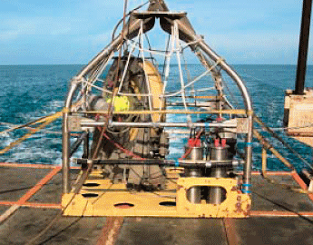 Figure 90 |
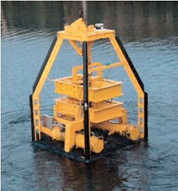
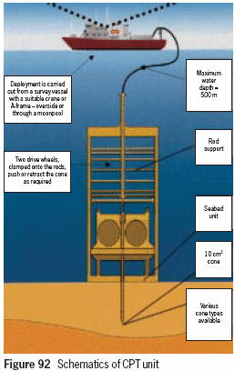
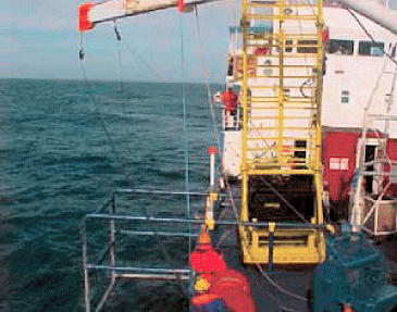
| Wheel-drive CPT units These marine CPT units (Figure 91) are based on a wheel drive system and the straight rod as used in conventional land based CPT testing. The straight rods are clamped between two pairs of driving wheels which rotate, pushing the rods into the ground. The units typically come in a range of sizes from 2 tonnes up to 20 tonnes. The units are lowered to the seabed from a vessel by using an auxiliary winch and wire; the CPT system is linked to base by a separate umbilical cable or by acoustic modems in deepwater environments. The system is typically capable of operating in water depths of up to 2000 m. It can be configured to achieve penetration depths of up to 40 m below seabed level. However, this is dependent upon the tested soils and available handling systems. Figure 92 shows the schematics of these units. The wheel-drive CPT system consists of a seabed reaction frame incorporating a wheel-drive mechanism, and electronic control and data acquisition systems. Each drive unit comprises four wheels which clamp onto the cone thrust rods to push the rods into the ground. Power is provided from the support vessel at the surface and transmitted via an umbilical cable to the unit at the seabed. All data output from the cone is transmitted back up the same cable to the data logger and laptop on the support vessel. A rod support tower is attached to the lift line and frame unit. This guides and supports the thrust rods within the water for the depth of test required. As the drive wheels are rotated against the thrust rod, so the cone is pushed into and through the seabed soils. As with conventional CPTs, the push rate is 20 mm/sec. The reaction weight for the test is provided by the weight of the seabed unit itself. |
|
| | |
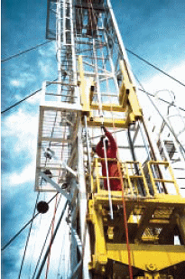 Figure 94 Figure 94 | Down-hole CPT system The down-hole cone penetration test system enables a CPT test to be performed in-situ from the base of a borehole, either offshore or on land, allowing soil parameters to be measured. The advantage is that in water where a deeper penetration is required, the wire-line CPT tool can be deployed down a drill pipe to perform either a 1 or 3 m CPT. One such wire-line CPT tool is the WISON-APB, manufactured by A P van den Berg. Figure 94 shows a drill rig with the CPT tool. On completion of each CPT test the borehole is advanced. The CPT tool can then be deployed down the drill pipe again to perform the next CPT test. The CPT test in combination with a drill pipe allows testing at great depth. Equipment The equipment differs from a conventional CPT in that the tool is remote from the surface, attached and controlled by an umbilical winch (Figure 95). The umbilical cable houses a hydraulic hose which powers the tool and the communication cable so that the test results can be seen in real time. Using this method, tests can typically be performed down to a depth of 600 m. |
| The tool consists of a down-hole jacking unit with a 3 m stroke and a thrust capacity of up to 100 kN. This system enables the borehole to be advanced and CPTs be performed at all depths to obtain information from below the proposed foundation depths.  Figure 95 Testing The system is used in conjunction with a rotary drilling system and open bit. After the borehole has been advanced to the required test level, it is cleaned by mud flushing. The tool is lowered by its self-tensioning winch to the bit, where it seats and latches under its own weight. The operator starts the test from the control cabin and the cone penetrometer is hydraulically pushed into the soil at a constant rate of 20 mm/sec. The movement of a hydraulic ram on the winch, logs the depth which is proportional to the movement of the cone. Throughout the test the measurements of cone tip resistance, sleeve friction and pore water pressure are displayed graphically in the control cabin. The data is converted to a digital signal prior to transmission up the umbilical by a down-hole data acquisition unit. Upon reaching the maximum achievable stroke of 1 or 3 m, or the limiting thrust capacity of 100 kN, the test is terminated. Reaction force During the test, sufficient reaction force is required to balance the penetration thrust. If this is not available from the drill string alone, the system may be used in conjunction with a seabed reaction frame which clamps onto the drill string. Cone penetrometer type There is a wide selection of probes that can be used for different purposes. These are detailed below. |
| Cone tips and sensors: | friction cone | |
| temperature cone | ||
| piezocone | ||
| seismic piezocone | ||
| electrical conductivity cone | ||
| | ||