Chapter 4
Part 1: Special cones: geotechnical cones
Seismic cone
| SEISMIC CONE 4.3 | |
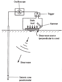
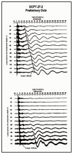
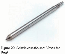
 Figure 21 Seismic cone configuration (above), test result (below)  | Ground surface motions The seismic cone (Figure 20) measures the shear wave velocity of the soil being investigated. Together with a knowledge of the soil saturated unit weight, the shear wave velocity allows an assessment of the small strain shear modulus (G0) and the constrained modulus (M0) to be made. The small strain shear modulus is an essential input for rediction of groundsurface motions from earthquake excitation, evaluation of foundations for vibrating equipment, offshore structures ehaviour during wave loading, and for prediction of deformations around excavations. Equipment The seismic cone is available in 10 and 15 cm2 areas. The cone usually consists of a piezocone unit – measuring the geotechnical parameters qc, fs and U2 – with a receiver for the seismic measurements above it. A schematic diagram, with the layout of the standard technique using a seismic cone, is shown in Figure 21. The extra equipment needed, in addition to the built in seismometer, is a memory oscilloscope and an impulse source with a trigger for the oscilloscope. The source can consist of a steel beam for shear (S) wave generation or a flat plate for compression (P) wave generation.  |
| The moduli G0 and M0 can be determined from the following: G0 = ρ(Vs)2 (kN/m2) M0= ρ(Vp)2 (kN/m2) where: ρ = the soil mass density (kg/m3) Vs = shear wave velocity (m/sec) Vp = compression wave velocity (m/sec) Method The shear wave source usually consists of a beam pressed against the ground by the weight of the CPT vehicle and a hammer. Normally the seismic cone penetrometer is pushed into the ground and penetration is stopped at 1 m intervals. During the pause in penetration, a shear wave is generated at the ground surface and the time required for the shear wave to reach the seismometer in the cone penetrometer is measured. The shear wave is generated by hitting the beam end horizontally with the hammer in the direction of the long axis. The computer in the CPT rig collects and processes all the data from the CPT or CPTU. The seismic source for offshore testing is a hydraulic underwater shear wave box. Sonic cone Lankelma Ltd is developing a new seismic tool for cone penetration testing. The sonic cone will allow in-situ testing of primary and shear waves without a surface source. It combines a standard piezocone with an acoustic velocity-logging tool. Acoustic velocity logging uses mechanical energy in the form of pulses or continuous waves of acoustical frequencies to investigate the surrounding material. The simplest form of the sonic logging tool involves an acoustic pulse travelling from the transmitter through the soil, as a compression (P) wave, to the receiver which is a fixed distance from the transmitter. The pulse also travels up along the wall of the housing as a boundary wave. |
